
Shortly after planning the three crossings that make up the PRR/N&W interlocking, I discovered that the section of the N&W that I thought was straight, wasn’t. The problem was that the easements of the curves at either end of the straight were creeping in, so both ends of the straight were actually a very slight curve.
My takeaway from this discovery was that while spline roadbed can be allowed to make its own spiral easements in most cases, in other cases specific ROW locations need to be enforced. I didn’t do that when building this section, so I was forced to retrofit the correct alignment.
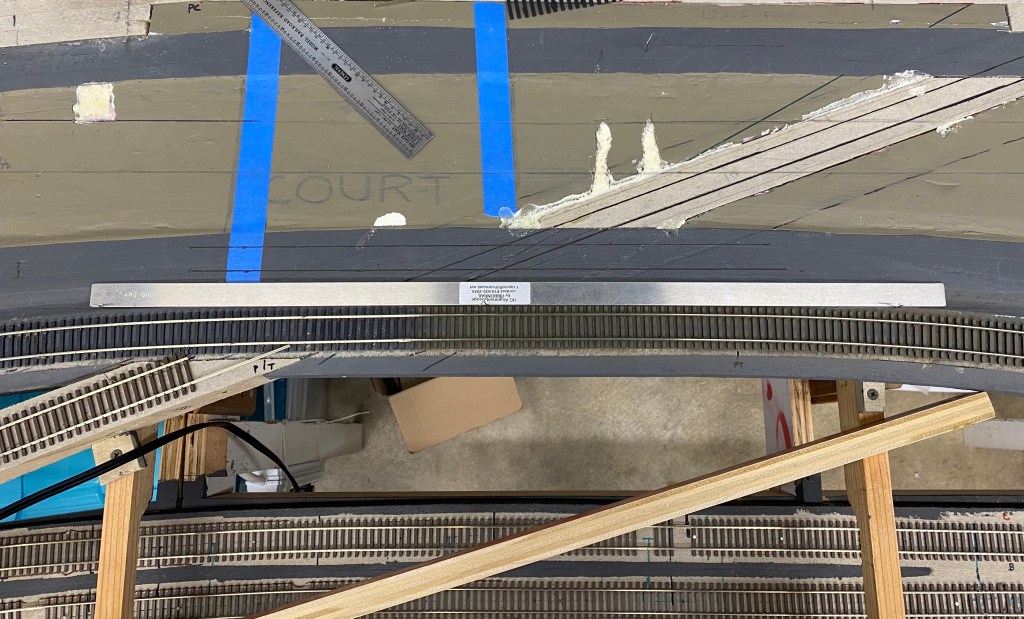
In the image above, the two-foot straight edge illustrates the slight bend. To fix it and avoid building a crossing across a curve, I decided to reposition the curves on either end and shorten the spirals. This ended up affecting about ten feet of track.

My first attempt was to leave the apex of the curves in the same place but broaden the curve’s exit, which lead to a shorter spiral. I used the bent-stick approach for this. The image above shows a 30″ radius curve template sitting partially in the fixed radius part of the curve, with the rail easing away from the fixed radius between the second and third hole in the template. From this image, you can see the easement is long and quite lazy about getting to tangent (it made for really smooth running though).
I wasn’t happy with this solution because it led to too many radii within one curve, so instead I chose to push the apex of the curve toward the center of the right of way about an inch, extended the 30″ radius arc a bit further, and used an spiral that was about 8″ shorter. Effectively, this made the curve more “square” – starting later and ending sooner.
The result of those changes lengthened the straight about 6″ on the left end, and applying the same approach at the right end of the tangent found another 8″.

The photo above shows the result of the changes on the right end. The offset of the tangent and the 30″ curve radius is about 3/4″, down from about 2″ with the lazy spirals. The length of the spirals is around 18″, which feels right.
Looking closely at the photo above, you can see the original and new point of tangent and the new spiral point marked on the ballast shoulder.

The new alignment of the straight is a full two feet long, which puts the crossing in a much better position. The Sharpies point to the original ends of the straight for comparison. Notice the gap in the rail – the realignment also increased my length of run by an inch!

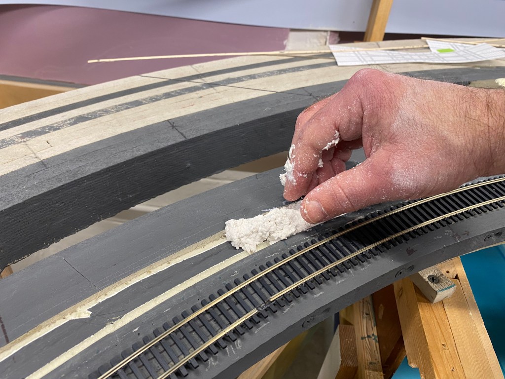

Squaring off the curves (as the racers would say) made the new track alignment cross a depression in the center of the roadbed that represented the ballast profile between the two tracks. I had to fill that in to provide a foundation for the new alignment (and as I later learned, a center “ditch” isn’t prototypical anyway). My wife and I cut out some of the foam that formed the center profile, filled it with Sculptamold, and repainted it in my base “cinder” color.

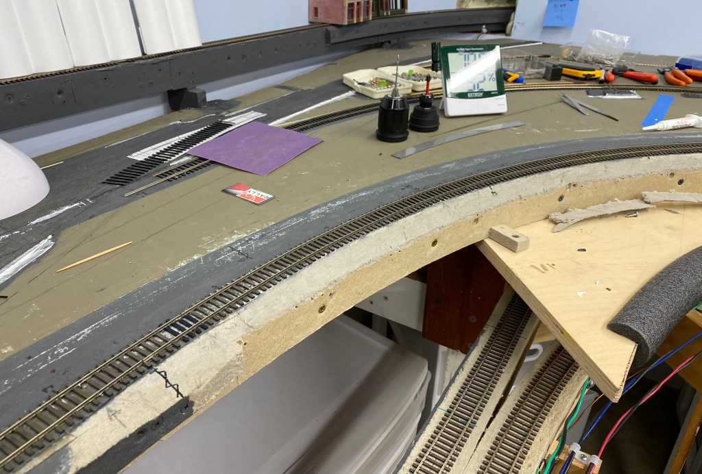
This image does a good job of showing how much the curve moved outward compared to the light-colored line that is an artifact of the old alignment. That movement exposed almost an inch of the roadbed at the apex of the curve and required some rework to remove the excess material and regain my ballast shoulder.

I removed the existing ballast shoulder (a separate piece of Homasote screwed to the side of the spline) and cut away unneeded material with my favorite Homasote-working tool – an oscillating saw with a metal cutting blade. I eyeballed the angle, and it worked out pretty well. Including cleanup, it took about ten minutes per side.
All that’s left now is to repaint the new ballast shoulder, then it’s on to building the three crossings!
Thanks for reading my blog. If you have any questions or additions, please share a comment in the section below. If you know others that might be interested in this blog, feel free to share the link.
